This project page provides a guide to adding both USB and a Web based User Interface (UI) to remote control socket set. Through the process we will unlock even more capabilities than are available when you use the socket set as they were originally intended. Part 1 deals with the hardware, Part 2 (this post) deals with programming the chip and Web UI.
The main components are:
- Arduino (or other AVR-MK2 programmer)
- Web-server (I used a Raspberry pi, but any computer will work if it’s running Apache and PHP)
- Lego (if you want to make a Raspberry pi case)
Okay, first step is to program the AT Mega 8 chip.
I don’t have a AVR-MK2 programmer like [befinitiv], but I do have a number of Arduino boards. There are a number of ways to program an AT Mega 8 with an Arduino, but the most successful method I have found is to use mega-isp code for Arduino. A very good tutorial can be found at [blog.ntsd.net]. Upload mega-isp onto your Arduino.
mega-isp: programming an atmega8 with arduino from [web archive – blog.ntsd.net]
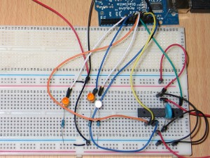
If you would like to program the chip before you have soldered it all together, follow the instructions above. If you have the hardware already assembled use the programming cable (purple, grey, white, black) that sticks out the of the remote control at the end of the first tutorial (see image below).
In this case the purple is reset (Arduino pin 10), grey (Arduino pin 13), white (Arduino pin 12), black (Arduino pin 11).
Using a Linux machine with avrdude installed run the following command in the terminal
$ avrdude -p atmega8 -c avrisp -P /dev/ttyUSB0 -b 19200 -U lfuse:w:0xe4:m -U hfuse:w:0xda:m
This is a combination of the standard setup for mega-isp and setting the fuses as done by [befinitiv]. The ttyUSB0 in the code above is the Arduino, so this may need to be changed, but if you unplug all USB peripherals and plug in the Arduino first it should be ttyUSB0.
- Plug in the remote control and hook up to the Arduino as mentioned above.
- Now download the code from my gitHub repository.
- Navigate to the folder “remote_controlled_socket” in the terminal.
- Run make.
- Now run make program
The code above largely builds on the code provided by [befinitiv], but adds extra support for up to 15 devices and adds channel selection to the mix.
Okay, now we have the remote all set up it’s time to set up the web based control. Essentially what we need here is a basic web server running PHP. Place the files from the “SerialPowerControl-web” folder on the server. As I’m running a Linux server so I have to alter the dialout group settings to allow the PHP script to communicate over the USB.
$ sudo pico /etc/group
-> add “,www-data” to end of dialout:x:*** (without quotes)
Now I’m using a Raspberry Pi as my server (as it’s a really cheap, low power and tiny computer) and I encountered a slight problem as the Apache server isn’t configured properly, to resolve the issue you need to do the following:
$ sudo groupadd www-data
$ sudo usermod -a -G www-data www-data
$ apt-get install php5-common libapache2-mod-php5 php5-cli
after installation, then restart Apache:
$ sudo service apache2 restart
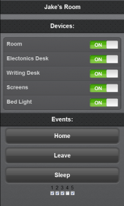
If eveything is successful you should end up with the interface as shown below (point the browser to the server location of the power scripts) and once the remote is plugged into the servers USB port (make sure it’s the first USB device plugged in, so that it becomes ttyUSB0). This was easily thrown together using PHP and the jQtouch library meaning it will work in any Webkit Browser (Chrome, Safari, iOS and Android), it still works in Firefox, but loses it’s visual appeal.
Feel free to edit the scripts on the server so that the text reflects your own set up. You can add more devices (up to 15 per channel), events or change the default channel (the check boxes at the bottom of the image above, there are 32 possible channels). Check out the README file that comes with the scripts for the mapping of device numbers and the settings on the sockets (4-bit code). Let me know in the comments how you get along, the changes you make, or the issues you encounter.
I think one of the next steps is to try and add manual control to the sockets, there is no switch on the socket itself. You can of course use the wall socket switch if available, but this completely disables the remote feature. I also have one socket circuit embedded in the light switch for the main room lights, again the actual switch will turn off the lights but also disables the remote feature. So the new feature will have to allow for manual control without disabling the remote feature.


[…] This project page provides a guide to adding both USB and aWeb based User Interface (UI) to remote control socket set. Through the process we will unlock even more capabilities than are available when you use the socket set as they were originally intended. Part 1 (this post) deals with the hardware, Part 2 deals with programming the chip and Web UI. […]
[…] [Jake] took some cheap hardware and figured out a way to use it as a huge home automation network. He’s chose a Raspberry Pi board to connect the radio controlled power outlets to his network. He wrote about his project in two parts, the first is hacking the RC outlet controller and the second is using the Raspberry Pi to manipulate it. […]
Great Job !!!
your design is very safe and does not depend on the computer used for the webserver, letting the microcontroller talk to the real world. Since the raspberryPi is equipped with GPIOs I guess you could have done without the FTDI cable and the arduino
Thanks Philippe!
Yeah, I’ve considered the use of the GPIOs on the Raspberry Pi and I’ll definitely look at doing something with them in the future (maybe add occupancy detection, so lights can be turned on/off when people enter/leave the room).
I suppose the plus of the approach here is that it’s more general and works across all devices with USB connectivity. For example I have a regular LAMP server at home and this method still works with it.
[…] » Adding web connectivity (via USB ) to remote controlled sockets – Part 2 (software) Jake Rowan … If you want to modify an inkjet printer or build your own inkjet plotter for the purposes of direct resist printing onto copper boards to make printed circuit boards, this is your group. In addition, we now explicitly cover inkjet printing of silver or other conductive coatings or metals directly onto substrates such as fabric, mylar, fiberglass boards, and other substances. As an adjunct to the Homebrew_PCBs list, this list is about design, construction, software, modifications, etc. necessary to inkjet print resist directly onto copper. Please post images, examples, software/firmware, etc. to Files and Photos. James Newton has put together sort of a FAQ of the subject by gathering together information from several people's successful inkjet conversions and posted them on his Massmind site . […]
I’ve just linked to this from the Pi Forums ,
Someone was asking how to control a mains device safely from a Pi .
http://www.raspberrypi.org/phpBB3/viewtopic.php?f=37&t=7855&p=98065#p98065
( very cool work btw , for both yourself and the guy who started it )
Hi
interesting post 🙂
But I have a question: where can I find the php script used ? 🙂
thansk
Max
Hi Max,
you can find it here:
https://github.com/jbyrne/SerialPowerControl/tree/master/SerialPowerControl-web
the link in the post seems to be broken now.
Enjoy and let me know how you get along 🙂
Jake
hi, i have an adruino uno compatoble device and i am Trying to load the bootloader into the ATMEGA 8. The link you have provided above (blog.ntsd.net) shows a blank website. I was wondering if you could show how you burn the bootloader to the ATMEGA 8 and if other ATMEGA would work just as well like the 168 or the 328.
Hi Kelvin,
the web archive is a great way of seeing a site that may no longer be available.
Here is the site:
http://web.archive.org/web/20121211084038/http://blog.ntsdt.net/?p=184
I hope that helps…
Yes.. Thank you. That helped
Hi Jake,
I am new to linux and raspberry pi. Thank you for your guidance so far.
(1)I would like to know how do you place the files into the server folder? How do you locate your server folder?
(2)I would also like to know if there is a command to see which ttyUSB the arduino is connect to.
Thank you for the help
Hi Kelvin,
The folder is usually: /var/www/
Here are a bunch of tutorials on setting up Raspberry Pi as a webserver:
http://www.instructables.com/id/Turning-your-Raspberry-Pi-into-a-personal-web-serv/?ALLSTEPS
http://www.penguintutor.com/linux/raspberrypi-webserver
http://www.element14.com/community/community/raspberry-pi/raspberrypi_projects/blog/2014/02/24/raspberry-pi-as-a-lamp-server
As stated in the post above:
Otherwise it will be something like ttyUSB1 or ttyUSB2
I hope that gets you closer.
Thank you.. that helped.. with regards to the usb. I had to use dmesg to identify . it turns out it was on ttyACM0 instead on ttyUSB0